George's Foreign Radios...

Last Updated on January 25, 2013

Translate to
Powered by

'Wells Coated' R.A.D 65 from London, England


Fig 1. - Reproduction Ekco AD65 Radio
    This radio was created by Gerald Wells in England in 1994. If you google his name (Gerry Wells), you will find several references as well as an interview of this very interesting fellow. It is my understanding that he made 52 of these in the 1990s. I saw number 6 come up to auction a few years ago, and missed it. This is number 16. It is an impressive radio! He had made additional sets, the more recent including an FM band.

    This radio is made of wood, and painted to look like colored bakelite.

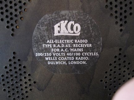
Fig 2. - The label on the back of the set
    Note the model number and manufacturer name on the label! Wells Coates was the designer of the original Ekco AD65. Gerry said he is Wells, and he "Coated" them (with paint).

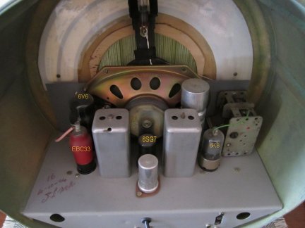
Fig 3. - The Inside of the R.A.D.65 Radio
    The inside of the radio is quite neat, and you can see the signature of Gerry Wells along with the unit number and the date.

    I tried to power up the radio, and it was intermittent and quite insensitive (1 AM station very weak). I decided to open up the radio and take out the chassis. Here are some photos of the insides.


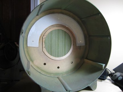
Fig 4. - The Inside of the R.A.D.65 Radio Cabinet
    You can see the MDF wood quite clearly. The tuning dial is glued in place. The chassis was to be supported by the two larger wooden wedges on the side. You can see two faint circles on each side of the controls. This is where wooden dowels were glued to the front to hold the chassis in the cab. The purpose of the two holes in the back of the chassis is to allow access to bolts imbedded in the dowels that the chassis is to be fastened to. You can see the two dowels attached to the chassis below. The glue must have failed over time or during shipment. You can see that there is lettle to hold the chassis if the radio were tipped upside down. Currently, the knobs (which are also wooden and painted) are the primary means of keeping the chassis in place..

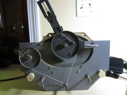
Fig 5. - The Front of the Chassis
    You can see the mechanics of how the dial pointer works. The chassis is formed from two sheets of metal; the front face, and the tube/valve mounting surface plus rear of chassis (bent). The chassis was then painted. And you can see the two dowels meant to hold the chassis in place.

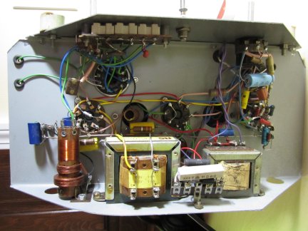
Fig 6. - The Underside of the Chassis
    Part of my problem is that the IF transformer (above the power transformer) has broken loose, and some wires may have come off. The core and windings were just dangling.

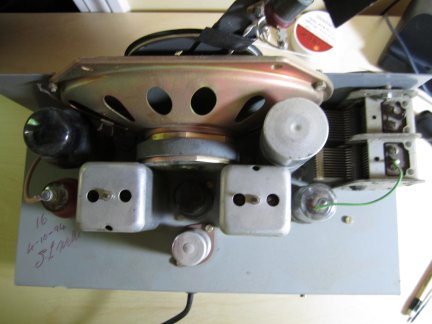
Fig 7. - The Chassis looking down from the Top
    An interesting fact is that all the tubes (Valves) in the radio were obviously used.. The 6V6 had the number scratched into the base, the 6SG7 had bits of rust, etc. I am sure that they were all serviceable.. I will need to trace out the circuit. I may write Gerry and see if there are any records of the schematics for this series of sets.

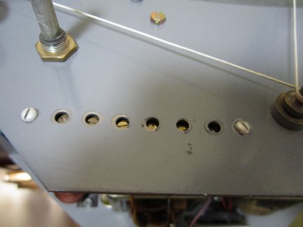
Fig 8. - The alignment trimmers on the front of the chassis.


Copyright © 2013 oldradios.com, All Rights Reserved. - Use this link to contact me